So I've had some research time with this box, and failures before I was able to make it work. Hopefully this will prevent others from spending excess money to get it to work.
So the box is made to work with an LS engine for those that want to run a carb. Software is the same that is used for the grid, although there are a couple things at least with the logging that isn't the same as the grid. It is made to work with either a 24 or a 58 tooth reluctor, but here is where the fun begins. The 24 tooth arrangement came with either a 1 pole cam plate machined on the cam, for 2005 only a one pole plate in the front. The front mount is the tricky part with the 24 tooth. The 58 tooth uses a 4 pole front mount plate. Cam gears for the front can be bought for single row chains or double roller with no poles, 1 pole, or 4 poles. Below is what you need to get it to work correctly.
1. Gen 3 users a 24 tooth reluctor on the crank. The crank sensor is GM 12560228, and is black in color. Looking at the connector on the sensor there is an alignment tab on the right side top. The cam sensor mounted on the rear of the block is a GM 12561211, I also found the AC Delco part number was 213-363. One of the two cam/crank sensor 10 pin harnesses supplied with the 6014 is shorter than the other, this has the correct connectors to fit each sensor and is the right length. Both sensors are wired to the pink wire in the harness for 12 volts. Cam gear has no poles machined or plate mounted to it.
2. Gen 4 engines after 2005, I am going to skip to the 58 tooth reluctor setup. The old sensor part number is GM 12585546, the new replacement number 12703627, either should work fine. Don't be confused by colors, one is black and one is gray. The alignment tab is on the left top. For the cam a front mounted sensor and 4 pole cam gear must be used. The sensor is a GM 12591720. With the VVT setup the plate is offset and uses a thicker timing cover to offset the sensor correctly. The non VVT gears use a thinner cover and set the sensor closer. The second 10 pin harness is much longer because of the separation between the cam and crank sensor. The shorter wired connector is the crank, longer is the cam. This setup has both the crank and cam sensors wired to the orange 5 volt wire and the correct connectors for the sensors.
3. 2005 Gen 4 engines, or any later Gen 4's with a 24 tooth reluctor and a front mount cam sensor. This is the tricky one, and the setup we ended up with. Crank was supposed to have a 58 tooth reluctor but didn't end that way. Crank sensor is the same as the Gen 3 above, GM 12560228 and as far as I've been able to find out needs 12 volts. The cam sensor is the same as the 58 tooth front mount, but with a 1 pole reluctor. This is made for 5 volts, and what I haven't found out is whether or not it will handle 12 volts. And the difference with the connectors makes both both harnesses incorrect, the short one is too short to fit the front cam sensor and neither wired for different voltages. What I ended up doing was taking the short harness apart and stealing the crank sensor connector and wires out of it. It has the longer wires of the two connectors and is about the same length in the other harness. First I cut away the heat shrink carefully, and pulled off the wrapping that tied the two cables together near the 10 pin connector. On the 10 pin connector I pulled the white insert out with needle nose players on the two hole in the middle, quick yank and it came out. There are tabs that hold each terminal in for the crank sensor, you move them away with a scribe and the wires come out with little twisting and turning. You will need to clip the cam sensor pink 12 volt power wire away from the split, and clip the black ground off the crank sensor at the spit. On the long 10 pin harness I repeated the same, cutting the shrink and unwrapping, pulling out the white piece in the connector. There are white blanks installed in unused spaces, pull the blank out where the pink went in the short harness, this is next to the orange 5 volt terminal/wire. Remove the crank sensor signal wire orange with a stripe, it's the shorter of the two wired connectors. Clip the solid orange 5 volt power wire from the crank sensor at the split, leaving the cam sensor connected thru to the 10 pin for 5 volt power. Clip the ground about an inch away from the split to allow splicing to the crank sensor wiring from the other harness. Then put the crank sensor terminal you removed from the other harness in, and then the pink 12 volt wire in next to the orange. Splice the ground wires together, rewrap the harness and tape it up. I used rescue tape, self sealing and adhesive. So you end up with the crank sensor at 12 volts, cam sensor at 5 volts as they were designed. It fired right away when finished.
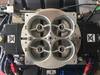
Chevy LS MSD 6014
1 post
• Page 1 of 1
Chevy LS MSD 6014
![]() by jmarkaudio » Fri Jun 19, 2020 4:14 am
by jmarkaudio » Fri Jun 19, 2020 4:14 am
-
jmarkaudio - Posts: 177
- Joined: Sat Apr 13, 2019 2:14 pm
1 post
• Page 1 of 1
Who is online
Users browsing this forum: No registered users and 1 guest